White Rodgers 1F95-0671 Installation Manual
Browse online or download Installation Manual for Thermostats White Rodgers 1F95-0671. White Rodgers 1F95-0671 Installation and Operation Instructions User Manual
- Page / 16
- Table of contents
- TROUBLESHOOTING
- BOOKMARKS
- APPLICATIONS 1
- SPECIFICATIONS 1
- INSTALLATION 2
- WIRING DIAGRAMS 3
- WIRING DIAGRAMS 4
- THERMOSTAT QUICK REFERENCE 5
- INSTALLER/CONFIGURATION MENU 6
- Fan Operation 9
- Check Thermostat Operation 9
- Heating System 9
- OPERATING YOUR THERMOSTAT 10
- PROGRAMMING 10
- PROGRAMMING 11
- TROUBLESHOOTING 14
- White-Rodgers is a business 16
- The Emerson logo is a 16
Summary of Contents
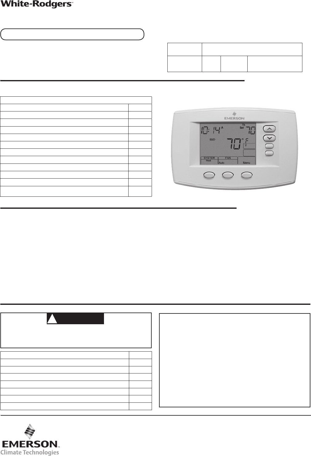
Blue Universal Thermostatwith Automatic Heat/CoolChangeover OptionModel Programming Choices1F95-06717 Day 5/1/1 Day Non-ProgrammablePART NO. 37-6979BR
10To prevent compressor and/or property damage, if the outdoor temperature is below 50°F, DO NOT operate the cooling system.CAUTION!Cooling System1.
11 PROGRAMMINGEnergy Saving Factory Pre-ProgramThe 1F95-0671 thermostats are programmed with the energy saving settings shown in the table below for
12Automatic Daylight Saving CalculationThe Real Time Clock will adjust automatically for daylight sav-ings time, in the following manner:Increment one
13Wired Remote Temperature SensingOne remote temperature sensor can be installed indoor or outdoor and connected to the thermostat by a maximum cable
14Symptom Possible Cause Corrective ActionNo Heat/No Cool/No Fan (common problems)1. Blown fuse or tripped circuit breaker. 2. Furnace power switch to
15NOTES
HOMEOWNER HELP LINE: 1-800-284-2925White-Rodgers is a business of Emerson Electric Co.The Emerson logo is a trademark and service mark of Emerson El
2Remove Old ThermostatBefore removing wires from old thermostat, mark wires for terminal identification so the proper connections will be made to the n
3 WIRING DIAGRAMSFigure 2 – Single Stage or Multi-Stage System (No Heat Pump) with Single TransformerSingleStage 1(SS1)Multi-Stage 2(MS2)OEnergized
4Single Stage3-wireZone ValveapplicationBlower/CirculatorFan EnergizedOpensValve(4)Constant24 Volt(Com-mon)24 Volt(Hot)CoolSystem6YWCRCCLASS IITRANSFO
5Programming and Configuration Items 1 "System On" indicates when heating or cooling stage is energized. "System On +2" indicate
6INSTALLER/CONFIGURATION MENU Thermostat must be in Heat, Cool or Auto. Press and hold the Menu button for at least 5 seconds. The display will show i
7 INSTALLER/CONFIGURATION MENU21 20 18 MENU dS (On) Off Selects Automatic Daylight Saving Time option22 21 19 MENU (OFF)Keypad LockoutL, P, Limit Se
8INSTALLER/CONFIGURATION MENU 5, 6 & 7) Cycle Rate Selection – The factory default setting for Heat and Cool modes, SS1, MS2, is medium cycle (ME)
9 INSTALLER/CONFIGURATION MENU24) Limited Cool Range – This feature provide a minimum setpoint temperature for cool. The default setting is 45°F. I
Related products and manuals for Thermostats White Rodgers 1F95-0671
 (1 pages)
 (8 pages)
 (4 pages)
© 2020, manymanuals.com. All rights reserved. | 1.104 s |
 Manymanuals.com
 Manymanuals.de
 Manymanuals.fr
 Manymanuals.it
 Manymanuals.pl
 Manymanuals.cz
 Manymanuals.es
 Manymanuals-pt.com
Comments to this Manuals