WHITE-RODGERS
1E30-373
LOW VOLTAGE THERMOSTAT
INSTALLATION INSTRUCTIONS
This low voltage room thermostat has open on rise switch
action and is designed for use on various types of heating
plants. It is equipped with a adjustable heater which may be
adjusted for primary control current draws of .15 to 1.0
Amps. A locking cover and kit of 4 alien screws and wrench is
provided to prevent tampering.
SPECIFICATIONS
Switch Rating:
Heating: 1.0a at 30vac max.
Heating Anticipator; .15 to 1.0a
Range: 35°F to 75°F
SELECTING LOCATION
The proper location of the room thermostat is most
important to insure that it will provide a comfortable home
temperature. Observe the following general rules when
selecting a location:
‘1. Locate it about 5 ft. above the floor.
2. Install it on a partitioning wall, not on an outside wall.
3. Never expose it to direct light from lamps, sun, fireplaces,
etc.
4. Avoid locations close to doors that lead outside, windows,
or adjoining outside walls.
5. Avoid locations close to radiators, warm air registers, or in
the direct path of heat from them.
6. Make sure there are no pipes or duct work in that part of
the wall chosen for the thermostat location.
7. Never locate it in a room that is warmer or cooler than the
rest of the home, such as the kitchen.
8. The living or dining room is normally a good location,
provided there is no cooking range or refrigerator on
opposite side of wall.
ROUTING WIRES TO LOCATION
1. Before drilling hole in wall at selected location, take up
quarter round and drill a small guide hole for sighting.
From basement, drill 3/4” hole in partition floor next to
guide hole. (On basementless houses, drill 1/2” hole
through ceiling above partition.)
Probe for obstructions in the partition. Then drill 1/2” hole
through wall at selected location.
___
---------------
—
-----------------------------------
MOUNTING THERMOSTAT
3. Through this hole in wall drop a light chain, or 6” chain
attached to a strong cord, and snag cord with hooked wire
from basement. (On basementless houses, drop cord
from ceiling and snag if at the thermostat location).
4. Attach thermostat cable to cord and pull cable through
hole in wall so that 6” of cable protrudes.
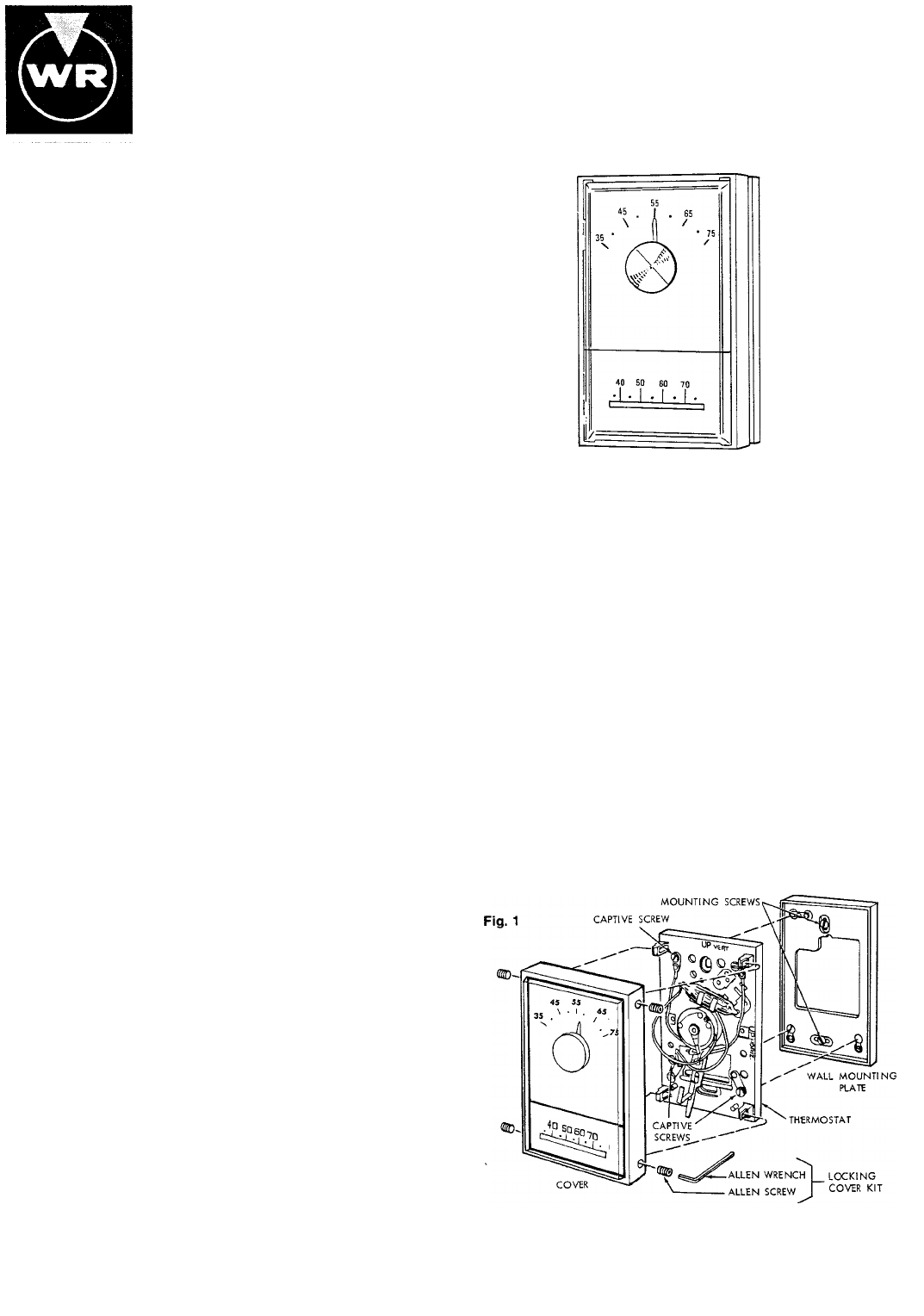
1. Pull thermostat wires through large hole in center of wall
mounting plate and fasten wires beneath two terminal
screws on bottom side of plate, (fig. 1)
2. Push excess wire into wall or switch box and plug up hole
to prevent drafts from affecting thermostat operation.
3. Thermostat must be ievei to assure optimum
performance. Place level on top of wall mounting plate
and mark hole locations for mounting screws. Attach
plate loosly to wall with the two screws provided. Again
place level on top of plate to be sure it is level. Then
tighten screws.
4. Remove cover from thermostat base by pulling outward.
Remove and discard pad (shipping protection forswitch).
Place thermostat base onto wall mounting plate and
tighten all three captive screws securely. Install
thermostat cover and tighten all four alien screws down
with wrench to prevent tampering.
Is
WHITE-RODGERS DIVISION
EMERSON ELECTRIC CO.
9797 REAVIS ROAD
ST, LOUIS, MISSOURI 63123
Printed in U.S.A.
PART No. 37-3479B
Replace 37-3479
8904
 (3 pages)
 Manymanuals.com
 Manymanuals.de
 Manymanuals.fr
 Manymanuals.it
 Manymanuals.pl
 Manymanuals.cz
 Manymanuals.es
 Manymanuals-pt.com
Comments to this Manuals