White-rodgers 1F94-80 User Manual

Browse online or download User Manual for Control panel White-rodgers 1F94-80. White Rodgers 1F94-80 User Manual

  • Download
  • Add to my manuals
  • Print
  • Page
    / 8
  • Table of contents
  • TROUBLESHOOTING
  • BOOKMARKS
  • Rated. / 5. Based on customer reviews
Page view 0
Printed in U.S.A.
This wall-mounted, low voltage thermostat maintains
room temperature by controlling the operation of multi-
stage systems. Use this thermostat for applications re-
quiring up to two stages of heat and/or cool. Indicator
lights show the system status. The user will program two
time/temperature settings per 24 hour period. The ther-
mostat stores programs for seven independent days. The
thermostat will store both heating and cooling programs
simultaneously. A 9 volt Energizer
®
battery will maintain
the stored program for approximately one week, if incom-
ing power should fail. If power failure is extensive and the
program is lost, after power restoration, the thermostat
will automatically maintain a factory preprogrammed heat-
ing temperature of 64°F or a cooling temperature of 82°F.
PART NO. 37-5185A
9329
PRECAUTIONS
Operator: Save these instructions for future use!
WHITE-RODGERS DIVISION
EMERSON ELECTRIC CO.
9797 REAVIS ROAD
ST. LOUIS, MISSOURI 63123-5398
FAILURE TO READ AND FOLLOW ALL INSTRUCTIONS CAREFULLY
BEFORE INSTALLING OR OPERATING THIS CONTROL COULD CAUSE
PERSONAL INJURY AND/OR PROPERTY DAMAGE.
WHITE-RODGERS
1F94-80
Multi-stage Electronic Digital Thermostat
If in doubt about whether your wiring is millivolt, line, or low
voltage, have it inspected by a qualified heating and air
conditioning contractor, electrician, or someone familiar
with basic electricity and wiring.
Do not exceed the specification ratings.
DESCRIPTION
All wiring must conform to local and national electrical
codes and ordinances.
This control is a precision instrument, and should be
handled carefully. Rough handling or distorting compo-
nents could cause the control to malfunction.
To prevent electrical shock and/or equipment
damage, disconnect electric power to system, at
main fuse or circuit breaker box, until installation
is complete.
Do not use on circuits exceeding specified volt-
age. Higher voltage will damage control and
could cause shock or fire hazard.
Do not short out terminals on gas valve or pri-
mary control to test. Short or incorrect wiring will
burn out thermostat and could cause personal
injury and/or property damage.
CAUTION
!
WARNING
!
R
CONTENTS
Description ......................................................... 1
Precautions ........................................................ 1
Specifications ..................................................... 2
Installation.......................................................... 2
New Installation
Select Thermostat Location
Route Wires to Location
Replacement Installation
Remove Old Thermostat
Attach Subbase to Wall
Attach Thermostat to Subbase
Operation ........................................................... 5
System Configuration
Set Option Switches
Check Thermostat Operation
Fan Operation
Heating System
Cooling System
Troubleshooting
INSTALLATION INSTRUCTIONS
Page view 0
1 2 3 4 5 6 7 8

Summary of Contents

Page 1 - WHITE-RODGERS

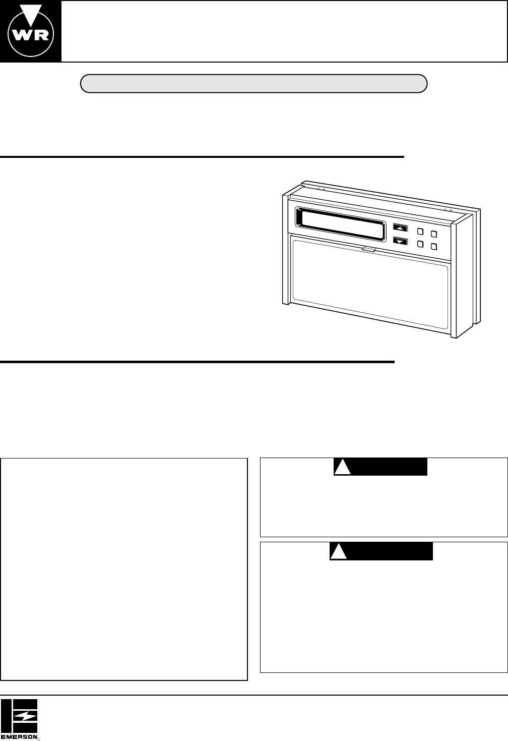
Printed in U.S.A.This wall-mounted, low voltage thermostat maintainsroom temperature by controlling the operation of multi-stage systems. Use this the

Page 2 - NEW INSTALLATION

2ELECTRICAL DATAElectrical Rating:20 to 30v AC 50/60 Hz.0.01 to 1.5 Amps (Load per terminal)2.5 Amps Maximum Total Load (All terminals combined)An

Page 3 - REPLACEMENT INSTALLATION

3REPLACEMENT INSTALLATIONREMOVE OLD THERMOSTAT1. Shut off electricity at the main fuse box until installa-tion is complete. Verify power is off with a

Page 4 - Figure 3. Subbase

42. Connect wires beneath terminal screws on sub-base using appropriate wiring schematic (see figs.3 through 6).3. Place subbase over hole in wall an

Page 5 - THERMOSTAT

5IF SAFETY CIRCUITS ARE IN ONLY ONE OF THESYSTEMS, REMOVE THE TRANSFORMER OF THESYSTEM WITH NO SAFETY CIRCUITS.NOTERelay contacts shown are thermostat

Page 6 - SYSTEM CONFIGURATION

6ATTACH THERMOSTAT TO SUBBASEWE RECOMMEND THAT YOU SET OPTION SWITCHESTO DESIRED POSITION BEFORE ATTACHING ONSUBBASE (see OPERATION). WE ALSO RECOM-ME

Page 7 - TROUBLESHOOTING

7CHECK THERMOSTAT OPERATIONFAN OPERATION1. Turn on power to the system. If the auxiliary heatsource has a standing pilot, be sure to light it.2. Press

Page 8 - WARRANTY INFORMATION

WARRANTY INFORMATIONTHIS WARRANTY STATEMENT SUPERSEDES ALL WARRANTYSTATEMENTS DATED PRIOR TO OCTOBER 1, 1991.White-Rodgers Division of Emerson Electri

Comments to this Manuals

No comments